Sunday, May 17, 2015

Reflection

Finalization & Presentation

_______   _______   _______   _______   _______   _______   _______   _______


Original DIY Practice Faceting Machine Drawing
Looking back the one regret I can say I have is that I didn't start building my machine soon enough which meant I couldn't give myself more time to get more into the small details and intricacies (even if I intended it to be DIY). I do wish I could have made an articulating arm rather than the O'Brien, but for this I aimed for more simplicity based off my experience with my attempted robotic hand project and how high I set the bar on that one only to not reach it. I want to move more into actually working with smaller motors and automations like the 3d printing machines. (I plan on building my own this summer.)

For Arts & Tech night I did my best to make my display interactive, even though I deemed my machine unsafe for the general public to just be playing around with, I tried to get them involved by other means. I brought in my books on faceting and had them turned to varying pages talking about the machine I worked on but also pages based on the art of Faceting to hopefully interest passerby's. I left notes on certain pages and told the audience that they were free to flip through them to their hearts desire. Included this was two individual Instagram accounts pulled up on my computer that served as perfect examples of home faceters and the results that they can achieve on a daily basis. Images of both unfinished and finished gems were shown in combination with my demonstration of the basics behind faceting. Outside of the machine I really felt confident having people approach me and ask me what I had done or what I was doing. I explained how I had built my machine and the structural concepts behind it. Yet what was always most intriguing to the observers were the results that my faceting machine produced. I felt people engaged in my demonstrations and that I was able to answer most all questions posed or refer them to a reading or source I knew of that could.

I really enjoyed working on this project and I feel that more than even in my school career I'm learning something that drives me to dig deeper. Although I was hesitant this semester to get completely involved electronically I anticipate the knowledge in the future. 


Creation, Assembly & Design Realization

Preparation, Box Creation, & Testing 

[Below are the assembly progress pictures with appropriate descriptions and explanations for design choices]
____  ____  ____  ____  ____  ____  ____  ____  ____  ____  ____  ____  ____  ____

Cutting & Creating The Box -- Finishing the Platform Design

I want to acknowledge my dad in this post. With his help and availability I was able to 

allocate the correct parts & wood for my project.

____________________________________________________________

Figure 1 : The Pieces
Using 3/4 inch plywood I determined an appropriate size for a box intended to hold the faceting machine. The outside dimensions are as follows: X = 17in , Y = 15in , Z = 8in . I made it this size with intentions to be economic when it comes to my supplies while also creating a big enough box to comfortably work on-top of/with. In retrospect, I could have made the box much shorter, maybe even down to 10in for the Y, as long as the bolt can still reach or extend through a bearing at an interior stabilization point (the inner-box).

Figure 2 : Fixed Sides

In Figure 1 you can see that I cut out and mitered at exactly 45 degrees the 6 sides (with the two inside sides) and arranged them in order of size with the altered faces on top. The farthest to the right we see the back side resting on top of the identical front. The back has holes to provide a surface for the motor to be screwed, secured, and adjusted horizontally along with a single hole for the plug to fit through the back. To the left of those are the bottom and top faces of the box. The top has a centered hole to provide clearance for the bolt that will pass through giving power to the sanding lap. Adjacent to them are the left and right sides of the box which are just slightly smaller than the top and bottom. The bottom and right side both have notches cut into them so that the final two pieces at the left of the picture can be slotted into for the inside box. I will bind and glue them all together ( placing the back and front on last) and then use the metal angle supports I have to reinforce the structure so it doesn't fall to pieces when I turn on the motor.

Figure 3 : Inner Box & Bearings
Putting the box frame together, shown in Figure 2, was used using wood glue held together with tape and then afterwards additional support was added through screwed in metal corner bracers. (Through some slight misjudgments and poor craftsmanship when it comes to drilling & my corners didn't meet perfectly but through some effort managed to be quite close.) You can see examples of gaps and overlaps that may exist when fixing the sides together in both Figure 2 & 3. Although the bracers may have slightly misaligned the box I feel that sacrificing some visual appeal for an ultra stable box is definitely worth it. After the frame I put the inner box sides together and then into place after determining that the bolt would stick and stay into the bearings seen in Figure 3. For the top of the box I used a square 5/8ths flange to brace the lap against the tabletop and lock it into place. For reference, considering the size of my box, my 10 inch 5/8ths bolt just reaches and rests in the flange bearing (i could have made it shorter). Once I made sure that it was a straight shot I placed my die pulley on and marked the correct hight so that I can fasten it tightly and know where exactly I had it when I come back to final assembly.


Figure 4 : First Assembly
Figure 5 : Motor Motor


Figure 6 : Motor & Pulley


After making sure the shaft/bolt was set straight, would work and was the correct length I moved on to fixing the back onto the box and making it so you could adjust the motor to make the belt taunt and functional. If you look back and take a look at my materials blog post, the motor has four slots in the back that are intended for this purpose specifically. I cut out long oval like shapes on the back side (see Figure 1) and also drilled holes through another individual large wooden block for the screws to tighten against, Figure 5. This allows me to be more accurate when it comes to tautness and is the simplest way to affix the motor to the box. Looking at the top of the box, containing the sanding disk, is what would be the lap on a normal faceting machine. I used a 4.5 in hook and loop sanding disk and glued and clamped it to the 4.5 in depressed center rubber panel with the bolt sandwiched tightly in-between. The bottom of the rubber panel is pulled down and fixed securely into place by the taps' in the flange bearings. Below in Figure 7 you can see that after glueing and clamping the rubber and velcro disks together I can attach and replace different sanding grits on top and when I tested it, it actually worked great with the insulating foam.
Figurer 7 : Foam Testing
After confirming that the set up that I created for the motor assembly worked and actually sanded the foam at a reasonable pace I moved on to adding the platform that I would need to emulate an O'Brien faceting machine. But first I'd like to say thanks to Calvin Rupnow for letting me use his wood stain, It was very dark and gave the wood a lot more personality.

In the three pictures below from left to right are: a close up of the stain on top of the box, The staff for the platform to to fixed to that I created out of the corner rails, and then the platform itself I created using some rail and wood including bolts for fastening to the rails.


Additionally, In order for this to be an O'Brien faceting machine I need to have a quill or pen that can have replaceable shapes, normally its just 5, 6 & 8 sides but I decided to include a few unusual ones like a triangle and square. One side of the pen has a screw and the other has a small bolt that the 2 nuts fit to. The side with the screw is representative of the glue that would hold the stone to the pen would this be a real faceting machine. 

And lastly, below was the final version of my 
DIY Practice Faceting Machine


My next and final blog post will be my reflection for this project.

Tuesday, April 28, 2015

Taking Action and Conceptualizing Construction Plans


Materials, Measurements, and Further Intentions

[Below are pictures, descriptions, and reasons for allocated parts, discussion of box design, & foam discussion.]
____  ____  ____  ____  ____  ____  ____  ____  ____  ____  ____  ____  ____  ____

Shopping Receipts for Pieces & Their Relations

After consulting Faceting for Amateurs, talking with Zachary Wright
& Frankie Flood, and researching the OBrien faceting machine, my father &
I went across town together visiting American Science and Surplus and Ace Hardware hunting for pieces.
______________________________________________________________

[List with discarded early tensioning idea, above]
     8   -   Large Corner Braces
     6   -   Small Corner Braces
     3   -   Black Hinges

These pieces above will be used to reinforce the box and for access doors.

     2   -   Plastic Bearings
     1   -   5/8th ID Bearing
     3   -   5/8th Bushings
     1   -   4.5 in Depressed Center Rubber Panel
~ That fits a 5/8th center bolt
     1   -   5/8th bolt ( 6in but I returned it for a 10in )
~ 4 washers, 3 nuts
     1   -   General Utility V-belt
     1   -   5/8th Die Cast Pulley

[I don't plan on using every part just nice to have some extras in case!]

     2   -   5/8th Flange Bearings
     1   -   5/8th Square Flange Bearing
     1   -   1/4hp Dayton Motor

After all this I also ordered items above online from McMaster-Carr and eBay...
_____________________________________________________

BOX

I sourced a sheet of 3/4 inch wood with 
Frankie's advice in mind.
I will need to cut, mate, glue, and nail it together.
Keeping in mind to place holes for the plug, table, and for tightening. 

____  ____  ____  ____  ____  ____  ____  ____  ____  ____  ____

FOAM

I've been thinking what foam will work best and I've decided to test a few.
I got some pink insulation foam from Home Depot and plan on cutting it into small cubes.
Also, I have some sprayable expanding & hardening foam that I may test by making small blobs.
Hopefully one of these will work otherwise I'll find another foam to test.

_____________________________________________________


I acquired this 1/4hp Dayton Motor from eBay before I knew the limit on motors and commonalities. (1/4hp max)
Hopefully I can get help from Zachary to make the motor run at lower speeds, otherwise it still works great... just fast. Rather than the idea above to make the v-belt taunt Frankie suggested that I make slots in the wood on the back of the box so that I can move, adjust, and tighten the motor to accommodate the belt.
 ____________________________________________________


Here is the depressed rubber pad intended for plane sanders. Although the 4 hole metal part fits 5/8th, it is not wider than the top of the bolt so I cannot use it and I had to out-source a square 5/8th flange that will be arriving in the next day or so. These pieces will take place bolted to the bottom of the disc (which I intend to make from wood at 5 or 6 inches wide & velcro.)
___________________________________________________


The 5/8th bolt I got above is 6 inches long and all of these bearings and pieces fit on it. The pulley is capable of being tightened down onto a specific spot on the bolt which will conserve space. (I've been advised that I may need to get a longer bolt, so I will purchase a 10 in bolt instead so that it will reach the inside box and bearing below that will provide it stability.)
 ___________________________________________________


 Left - The  large/small corner supports for the box, hinges, various screws and washers for assembly.
Center - These are what I will be screwing into the top of the box as rails for the platform design.
Right - Here the Die Cast Pulley and the V-belt are lined up giving size reference.
__________________________________________________

  Here are a few dry erase drawings courtesy of Frankie helping me determine how exactly to arrange the insides of the box.
He told me to fix the motor to the back of the box rather than the side and to build an interior box with bearings for the bolt.
Also we see the v-belt wrapped around the motor and pulley in the righ picture. 

_________________________________________________


These are the 3 flange bearings that I purchased in order to keep the spinning bolt in place and fixed to the wooden plate.
The bearings with two holes are actually 2 sides holding the center in a suspended placement.
Again, I'm waiting for the square flange bearing to make it to my house so that I can make final measurements.


_______________________________________________

Next post I will talk about the design and creation of the box
while focusing on the bolt, pulley, and table.

I will also begin allocating parts for and putting together the adjustable
Platform design along with the pen and the replaceable parts.

Foam shaping and experimentations will start taking place,
however I need to wait to apply my sanding disc and pads.
[This will most likely take place last.]

Have a good day!
Peace.


Saturday, April 25, 2015

Book Dissections & Extrapolation of Intentions

A Look In My Book and Stuff.

Faceting for Amateurs: 

[Below are four excerpts directly from Chapter 2 that I'm going to discuss in relation to the project and in general.]

_________________________________________________________________

"A faceting machine must enable the operator to place small flat surfaces, called facets, at various angles from 0 - 90 degrees. The machine should also facilitate the placement of these facets at any predetermined number of points around the circumference of the gem..."

http://gem-sphalerite.com/images_web/faceting/cutting_process/013_making_table_facet.jpg

          Enabling the operator is important in reaching all necessary angles. I want to recreate the flexibility as accurately as possible while blending different designs for simplicity. Zero degrees is necessary to get the 'table' (above) on the top of gems and is achieved through a perpendicular relative angle above the lap. Ninety degrees is just as important because if the gem is going to be set into jewelry the edge should be rounded and roughed so it can be gripped. Additionally, reaching all in-between angles will be accomplished through adjusting on the X and Y with multiple angle definers for accuracy. 

________________________________


"Any approach to precision [is] dependent upon the skill of the operator."

http://www.rockhounds.com/rockgem/articles/laplap3.jpg

          This quote is talking about how it doesn't really matter what machine you use, even if its a hand faceter (above) where you have to find the facet sides yourself. In the end it's up to the operator alone to determine accuracy for the cuts. Taking this into account I want to make my machine as straightforward and easy to operate as possible so that the public who has little to no faceting skill or knowledge could give it a try, learn something new and leave with a creation of their own as proof instead of becoming frustrated and instantly turned off to the idea.

_________________________________


"Any machine that places accuracy as a secondary criteria [isn't] very attractive to amateurs. The amateur cuts gems primarily for enjoyment and thus insists upon a close approximation of perfection."

http://upload.wikimedia.org/wikipedia/en/thumb/e/ee/Squarestone.jpg/220px-Squarestone.jpg

          Here again the book talks about accuracy and how important it is to be accurate when faceting. If a machine is too difficult to operate a beginner might become discouraged after multiple failed attempts. This discouragement is a direct result of them feeling like they're wasting time/effort/money, so if one were to make the entire process more simple and cheap less people would be opposed to attempting faceting. In order to resolve these concerns my practice faceting machine will remain easy to operate and the material that will be used (foam) will save money and time. A lot of hobbyists facet as a way to make additional income however, it's noted that enjoyment is the most common initial reason people get into faceting stones and that interest cant start if you've never been introduced.

_______________________________


"All [faceting machines] fall into one of two basic types, the mast and staff, and the platform. Each follows the same basic principal, but differs in constructional and operational details."

http://i749.photobucket.com/albums/xx138/miquel_bucket/P1050673.jpg

          The most common type of faceting machine is the Mast and Staff Arrangement (above) which is essentially an arm with joints that can hyperextend and hangs over the spinning lap. This structure is supported by X and Y rails placed alongside the lap so it can slide and swivel freely forward, back, up, and down to reach all the necessary angles. At the wrist of the arm theres a swivel point that allowing the operator the ability to check and pause work in-between cutting of the facets allowing the operator to gain more accuracy on the angles of the facets. There are many intricacies to the Mast and Staff Arrangement that allow the addition of angle cutting aids that can make faceting even easier. However, I do not plan to go for this design because of the complexities involved in creating the mechanical arm.

http://auctionimages.s3.amazonaws.com/59421/16138/5777283_35Z13TRFP.jpg

          The less popular, older, and the type of design that I chose for my practice faceting machine will be based off of a Platform Arrangement, specifically an O'Brien faceting machine (above). The only difference between these two arrangements is that rather than having an arm to reach angles, it's simplified even more to only a platform adjustable on the X and Y and a separate pen with calculated adjustable sided shapes on one end and foam on the other. Although the angles may be more abstract based off of the operators specifications, placement of the platform, and other process choices there are a lot of results that would otherwise be impossible to achieve with actual stone. This version of a faceting machine brings back a classic but simple design, making it more of a possible DIY project. This will also save time and effort in the production process for the machine hopefully encouraging additional interests.

_________________________________________________________________________________

[My Cliff Notes Version of...] 

The Abridged List of Desirable Faceting Machine Features.


(Again also borrowing from Faceting For Amateurs (Chapter 2, pg. 23-24))


http://www.usfacetersguild.org/articles/glenn_klein/against_the_stop/against_the_stop.gif (above)
http://www.theimage.com/faceting/12ultrlap.jpg (below)
  1. The construction of a smooth operating faceting machine is of prime importance.
  2. There should be interchangeable index gears. ( 5, 6, & 8 are the most popular)
  3. There should be clear crisp divisions of measurements, so as to be easy to read/record data.
  4. The quill (pen) should be adjustable to 90 degrees.
  5. The elevating device for the mast should work easily and have measurement clearly defined.
  6. A cheater for minor adjustments is invaluable when polishing. 
  7. The quill should also allow for the stone to be removed and examined.
  8. Angle-stops would be desirable to halt cutting at a certain point.
  9. The arbor must run true and be easily turned by a fractional horsepower motor. (1/4hp max)
  10. The machine should not be of great weight. Being heavy doesn't mean stable. (50 pounds max)
  11. A lap wheel of 6 inch diameter is quite satisfactory. (Enough space to cut an 100 carat gem)
  12. Power to the lap wheel should be delivered though a small cross section V-belt.
  13. If desired for portability it should be constructed/designed with this in mind.
  14. It should allow the operator to cut on both sides of the lap without changing its rotation.
  15. Some type of protection for the top arbor nut on the lap would be optimal.
Now I'm going to discuss how numbers 6, 7, 8, 14, and 15 may not apply exactly as they are explained above because of my decision to create an O'Brien style faceting machine rather than a mast and staff and because I'm creating mine for foam.

6. A cheater for minor adjustments will not be necessary since we will not be polishing the foam gems. Although it many be handy to realign the facet faces for the most part we wont be cutting the same one multiple times.

7. The platform style of an O'Brien faceting machine makes it so that the quill is readily removable and functions as its own piece. This removable quill (that I call the pen) will also have a fixable and removable piece within it that will be the only contact to the foam being cut.

8. Angle-stops (another cheater aspect of faceting machines) makes it so that when your cutting a side that the quill cannot go below the predetermined angle. In order to make the faceting process simpler I'm not sure if I'll include this. But if I do I may include it either on the pen or the platform.

14. I'm unsure if its a great idea to facet the foam on both sides of the lap or not. But since the pen is a completely separate piece it will be possible to reach both sides by manually adjusting and aiming and we can see if it is useful or even possible.

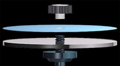
15. I intend to make the lap wheel out of wood and leave a space for the top of my screw to be flush. If this isn't possible I may just leave the convex top of the screw exposed which would only take a small portion of the lap up at the center.

http://metaphysicalstones.net/ART10.jpg


________________________________


For my next post I will include a list of materials and drawings.
Plans of designing, measuring and cutting out the box is my next step, then beginning assembly.

Thanks for reading! Peace.


Thursday, April 9, 2015

Gathering Research Process: Faceting Machine


Laying groundwork

For my machine that makes I intend on creating a specialized practice faceting machine. Faceting itself is a very specialized field focused on the transformation of gemstones into jewels and the equipment commonly used can be expensive and inaccessible to the general public. Additional necessary materials like diamond embedded laps of different grits, the gemstones, and the machines themselves can range in cost from thousands of dollars to a few hundred thrown together salvaged pieces. From what I've read on the differences between faceting machines, no matter what machine you're operating it is capable to produce a good result under the right circumstances and correct calculations. However, actual faceting machines are very dirty when used and are much more technical to operate along with waiting times between cutting phases for stones and the splash tray needing to be cleaned between cuts. This machine I intend on creating would be used as a practice tool for beginners learning faceting concepts. With simplified operation focused on the cutting of lighter foam-like material this practice faceting machine could save both time and money when learning faceting processes. 

Books

I began researching faceting and the machines used a few weeks before this project was presented in Digital Fabrication and Design by ordering multiple books on the art and technicalities involved with faceting and related gemstone practices. Although these books are more about the actual cutting of stones they include through explanations on other necessary details about faceting machines like a brief history and an explanation for variances on types (peg-board, O'Brien, and some modern cheaters) and the advantages and disadvantages. I'll include pictures from the two books themselves and list their information below. 

1. Faceting For Amateurs by Glenn & Martha Vargas ---- (all I can find are site's selling this book and recommending it, it is also not that expensive Amazon is a rip off.)

Called the "complete guide" Faceting For Amateurs is a book that covers everything that you could question about the art, culture, and practice of gemstone cutting (lapidary) and also the faceting machines operation with practical explanations. Although this book is dated 1969 it's easy to understand the reasons behind the classics being recommended as teaching devices as the machines and techniques haven't changed (unless you call automation a change). The main chapter of this book that I will accessing will be the twelve page second chapter that focuses only on faceting machines and even goes briefly over the standard brilliant cut. This chapter will help me look into the commonalities between faceting machines arrangement and the variances in arms for cutting allowing for comparison on styles.

2. Facet Cutters Handbook by Edward J. Soukup ---- (again all I find are site's selling this book paperback, which is the version I have.)

Although this book is almost entirely about the steps of actually cutting the facets into stones for a multitude of different cuts it has some important information pertaining to the doping process (which occurs during the initial placement of the stone on a rod and then also the transfer from one to another so that it remains square and cuts flat). This book also contains information about The Standard Brilliant Cut and the detailed steps involved in creating its shape. I plan on creating a machine that is for foam faceting and foam isn't something that could reflect light and actually have "brilliance" but the brilliant cut is the suggested first cut for beginners and I intend on attempting to create it as my first cut on the practice faceting machine.


Along with my books I have also been keeping a Pinterest that includes images and other online sources lending information on the build of a faceting machine or related complications.

For my next post I'll include a dissection of advice and insight from the books and the relation of those to the creation of my foam faceting machine.