Materials, Measurements, and Further Intentions
[Below are pictures, descriptions, and reasons for allocated parts, discussion of box design, & foam discussion.]
____ ____ ____ ____ ____ ____ ____ ____ ____ ____ ____ ____ ____ ____
Shopping Receipts for Pieces & Their Relations
After consulting Faceting for Amateurs, talking with Zachary Wright
& Frankie Flood, and researching the OBrien faceting machine, my father &
I went across town together visiting American Science and Surplus and Ace Hardware hunting for pieces.
______________________________________________________________
 |
| [List with discarded early tensioning idea, above] |
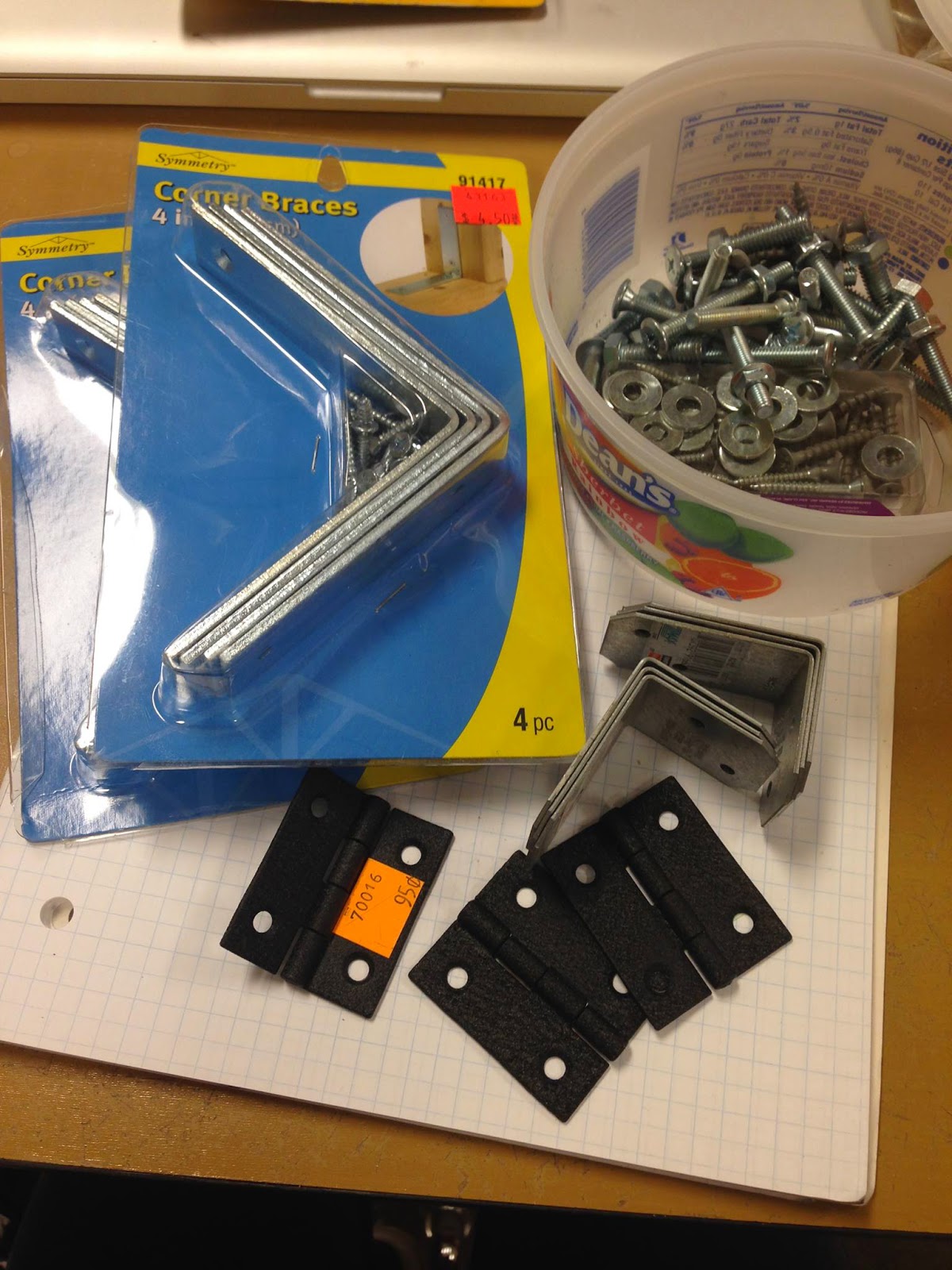
8 - Large Corner Braces
6 - Small Corner Braces
3 - Black Hinges
These pieces above will be used to reinforce the box and for access doors.
2 - Plastic Bearings
1 - 5/8th ID Bearing
3 - 5/8th Bushings
1 - 4.5 in Depressed Center Rubber Panel
~ That fits a 5/8th center bolt
1 - 5/8th bolt ( 6in but I returned it for a 10in )
~ 4 washers, 3 nuts
1 - General Utility V-belt
1 - 5/8th Die Cast Pulley
[I don't plan on using every part just nice to have some extras in case!]
2 - 5/8th Flange Bearings
1 - 5/8th Square Flange Bearing
1 - 1/4hp Dayton Motor
_____________________________________________________
BOX
I sourced a sheet of 3/4 inch wood with
Frankie's advice in mind.
I will need to cut, mate, glue, and nail it together.
Keeping in mind to place holes for the plug, table, and for tightening.
____ ____ ____ ____ ____ ____ ____ ____ ____ ____ ____
FOAM
I've been thinking what foam will work best and I've decided to test a few.
I got some pink insulation foam from Home Depot and plan on cutting it into small cubes.
Also, I have some sprayable expanding & hardening foam that I may test by making small blobs.
Hopefully one of these will work otherwise I'll find another foam to test.
_____________________________________________________

I acquired this 1/4hp Dayton Motor from eBay before I knew the limit on motors and commonalities. (1/4hp max)
Hopefully I can get help from Zachary to make the motor run at lower speeds, otherwise it still works great... just fast. Rather than the idea above to make the v-belt taunt Frankie suggested that I make slots in the wood on the back of the box so that I can move, adjust, and tighten the motor to accommodate the belt.
____________________________________________________
Here is the depressed rubber pad intended for plane sanders. Although the 4 hole metal part fits 5/8th, it is not wider than the top of the bolt so I cannot use it and I had to out-source a square 5/8th flange that will be arriving in the next day or so. These pieces will take place bolted to the bottom of the disc (which I intend to make from wood at 5 or 6 inches wide & velcro.)
___________________________________________________
The 5/8th bolt I got above is 6 inches long and all of these bearings and pieces fit on it. The pulley is capable of being tightened down onto a specific spot on the bolt which will conserve space. (I've been advised that I may need to get a longer bolt, so I will purchase a 10 in bolt instead so that it will reach the inside box and bearing below that will provide it stability.)
___________________________________________________
Left - The large/small corner supports for the box, hinges, various screws and washers for assembly.
Center - These are what I will be screwing into the top of the box as rails for the platform design.
Right - Here the Die Cast Pulley and the V-belt are lined up giving size reference.
__________________________________________________

 Here are a few dry erase drawings courtesy of Frankie helping me determine how exactly to arrange the insides of the box.
He told me to fix the motor to the back of the box rather than the side and to build an interior box with bearings for the bolt.
Also we see the v-belt wrapped around the motor and pulley in the righ picture.
_________________________________________________
These are the 3 flange bearings that I purchased in order to keep the spinning bolt in place and fixed to the wooden plate.
The bearings with two holes are actually 2 sides holding the center in a suspended placement.
Again, I'm waiting for the square flange bearing to make it to my house so that I can make final measurements.
_______________________________________________
The bearings with two holes are actually 2 sides holding the center in a suspended placement.
Again, I'm waiting for the square flange bearing to make it to my house so that I can make final measurements.
_______________________________________________
Next post I will talk about the design and creation of the box
while focusing on the bolt, pulley, and table.
I will also begin allocating parts for and putting together the adjustable
Platform design along with the pen and the replaceable parts.
Foam shaping and experimentations will start taking place,
however I need to wait to apply my sanding disc and pads.
[This will most likely take place last.]
Have a good day!
Peace.


